I got under the Ghia a bit tonight. From what I can see, the floor pans look pretty good. I do have a little concern with the passenger side. Definitely some damage to repair.
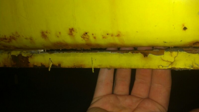

AKA Project Farfemmuven
I got under the Ghia a bit tonight. From what I can see, the floor pans look pretty good. I do have a little concern with the passenger side. Definitely some damage to repair.
Part ………….ft-lb …….size (dia x pitch)
Engine
Connecting rod nut -24 -m 9×1
Connecting rod capscrew -32 -m 9×1
Crankcase nut -14 -m8
Crankcase nut -25 -m 12×1.5
Cylinder head nut -8 -mm 18 m 8
Cylinder head nut -10- mm 23 m 10
Rockershaft nut -18 -m 8
Heat Exchanger at head -14- m 8
Muffler Clamp bolts -7 -m 6
Intake manifold nut -14 -m 8
Preheat-flange bolt -7 -m 6
Oil Pump nut -14 -m 8
Oil Pump nut -9 -m 6
Oil Drain plug -25- m 14×1.5
Oil Strainer nut -5 -m 6
Oil cooler nut -5 -m 6
Oil filler gland nut- 40
Flywheel Gland nut -235 -m 28×1.5
Clutch bolt -18 -m 8×1.5
Sparkplug -25 m -14×1.25
Engine to trans nut -22 -m 10
Crossmember bolt -18 -m 8
Crossmember bolt -29 -m 10
Generator pulley nut -43 -m 12×1.5
Fan nut -43 -m 12×1.5
Crankshaft pulley nut -32 -m 20×1.5
Crossmember to body -18 -m 8
Fan/Crankshaft pulley -94-108 -m 20×1.5
Front Axle and Steering
Front Beam to pan bolts -36
Body to beam bolts -14
Shock to beam sideplate -14-m 10
Shock to beam sideplate -25- m 12
Shock to lower torsion arm -25
Steering damper to front beam bolt -32
Steering damper to tie rod -18
Tie rod to castle nut -18
Tie rod nut -18
Clamp for tie rod bolt -11
Lock nut for torsion set screw -36
Wheel bearing clamp screw -10
Steering ball joint to knuckle -51
Steering box to front beam -22
Steering coupler to worm shaft -18
Pitman arm to shaft bolt -51
Locknut for pitman arm adj screw -18
Lock nut for worm spindle adj screw -42
Steering box housing cover bolt -18
Canceling ring to steering wheel -3.5
Steering wheel nut -36
Steering column to dash bolts -7
Column switch to attach plate -7
Column switch clamp to housing -7
Steering coupling flange to disc -11
Column to couple flange bolt -11
Manual Transaxle
Drive pinion round nut ball bearing -87
Drive pinion round nut roller bearing -144
Pionion retainer nut -36
Pinion nut -43
Drive shaft nut -43
Reverse lever guide bolt -14
Selector fork bolt -18
Gearshift housing nuts -11
Ring gear bolts – 43
Final drive cover nuts -22
Axle tube retainer nuts -14
Rear wheel bearing retainer nut -43
Oil drain plug -14
Oil filler plug -14
Rear axle shaft nut -217
Transaxle to frame bolt -166
Master cylinder
Stop screw in housing bolt -7
Residual pressure valve to housing -14
Brake light switch -14
Master cylinder to to frame bolts -18
Brake line to master cylinder -18
Front Brakes
Splash sheild to steering knuckle bolts -7
Wheel cylinder to backing plate -18
Caliper housing screw (disc brake) -18
Backing plate bolt -36
Caliper mounting bolts (disc brake) -29
Bleeder valve -9
Clamp nut screws -9
Hose to wheel cylinder/caliper -14
Rear Brakes
Wheel cylinder to backing plate- 22
Bearing housing bolts -43
Brake drum to axle bolt -253
Lug nut 14mm -94
Lug nut 12mm -72
Pedal assembly
Pedal bracket to frame -32
Pedal stop to frame bolts -18
I do have rear disc brake kits with emergency brake available for 1973 Ghia models, that is part number 22-2871.
I have added that listing to our E-store and you can find it here.
http://www.mofoco.com/item/
Please let me know what questions you might have or if you would like to place an order.
Thank you Paul
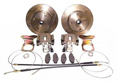
VW REAR DISC BRAKE CONVERSION KIT
Volkswagen rear disc brake conversion kit with emergency handbrake. Replace those old brake drums with new disc brakes!
For Beetles, Ghia’s, Buggys, and Sandrails. Fits Type 1 IRS 1973-1979
Kit includes:
These are for e-brakes!
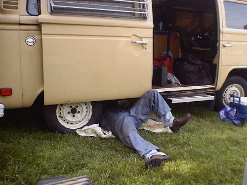
Day 4:
Let’s see if we can get those rear wheels spinning.


Hi Bonemaro,
Most modern motor oils are dangerous to our air-cooled engines. The ZDDP additives that allow the lifter-to-cam contact surfaces to survive have been removed or diminished in them as pollutants.
Valvoline VR-1 racing oil (technically being a “racing” and not street oil) has a good amount of ZDDP in it. Also, as opposed to true racing oils, VR-1 has anti-rust additives in it that make it usable for street use where we keep oil in the engine for long periods of time. Specially formulated racing oils are drained between races.
You might suppose that all oil just by itself is rust preventative, but it actually takes some good additives to make that true.
I’m sure other posters here have oil suggestions. I’d use 10w30 or maybe 10w40 under really hot conditions.
FJC
From http://type2.com/bartnik/tech1.htm#engine
This page is an attempt to empower you to fix your own VW and do it correctly. Unfortunately, there are not many mechanics that are familiar with the VW air-cooled engines anymore, and there are some that claim to be VW experts who are really just hacks. Also, since the price of labor to have your car fixed is not affordable to many, it makes good economic sense to learn how to do the work on your Volkswagen yourself.
This page is updated fairly often, and I will try to add as many articles as possible. I’ve been taking pictures of work I’ve done on my van so as soon as they get scanned, this will be like a mini-manual. I’m sure it will be nowhere near complete, but it will cover the more common and basic problems that can be easily fixed by the shadetree mechanic.
The first thing you need if you want to work on your own Volkswagen is a good set of manuals. I highly recommend those listed below.

In addition to those above, if you have a ’75 or later Beetle or Super Beetle, a ’75 or later Bus, or a ’67 and later Type 3, you should have fuel injection (assuming a US-spec model). In that case, a manual you will find very helpful is “How To Understand, Service and Modify Bosch Fuel Injection and Engine Management” by Charles O. Probst. It’s also put out by Robert Bentley Publishers, the same publisher as the official VW repair manuals. It covers all Bosch fuel injection systems, including the D-Jetronic system found on Type 3s and the L-Jetronic system found on Beetles, Super Beetles, and Buses.
Finally, before you begin wrenching, see this informative tool guide.
DISCLAIMER: Unfortunately, in these litigious times, some moron would probably try to sue me for something regarding the information on this page, so here’s the disclaimer. The procedures on this page are presented as guidelines ONLY. They reflect particular jobs that were done by myself or by another author and were written down from memory as a guide to others who might need to do the same procedure. I make no representations as to the accuracy of the information contained here (please remember that I am not a professional mechanic and that free advice is worth every cent). What you do to your car is what YOU do to your car. I take no responsibility for the results of YOUR actions, lack of common sense, or stupidity. The procedures below were written to help VW owners. They should always be used in conjunction with a good set of repair manuals, such as those mentioned above. Have a nice day.
Replacing rear brake shoes and wheel cylinders on a Bus.
Replacing the front brake pads on a Karmann Ghia.
Replacing the rear brake shoes on a Vanagon.
Replacing the parking brake cables on a Vanagon.
Replacing the master cylinder on a Karmann Ghia.
Replacing the clutch master cylinder on a Vanagon.
Replacing the clutch slave cylinder in a Vanagon.
Replacing the clutch in an early Vanagon or late Bus (with Type 4 air-cooled engine).
Removing and replacing the alternator on a ’72-’79 Bus.
Removing and replacing the starter on an air-cooled Volkswagen.
Starter troubleshooting procedure.
Replacing the points and condenser on an air-cooled Volkswagen engine.
Replacing the spark plugs on an air-cooled Volkswagen engine.
Hot-start relay installation instructions.
Ignition timing instructions for air-cooled Volkswagens.
Carburetor removal/replacement on a 1600cc dual port Type 1 engine (Beetle, Karmann Ghia, Thing, Super Beetle).
Engine and transmission removal/installation in an air-cooled, manual transmission Vanagon (1980-1983).
Thermostat replacement/installation on late Buses and early Vanagons with the Type 4 air-cooled engine.
Valve adjustment on a Type 1 engine.
Changing the oil on an air-cooled Volkswagen engine.
Replacing the pushrod tube oil seals on late Buses and early Vanagons with the Type 4 air-cooled engine.
Adjusting the automatic choke on carbureted air-cooled Volkswagen engines.
Adjusting the fan belt on the Type 1 engine.
Replacing the heater cables on an air-cooled Vanagon.
Removing/replacing the front axle beam on a late Bus.
What kind of gas should you be buying?
Removing/installing window glass on an air-cooled Volkswagen.
How to torque the rear axle nut without a torque wrench.
From http://type2.com/bartnik/valveadj.htm
APPLICATIONS: Volkswagen Type 1 engine, specifically the 1600cc version. This probably applies to other Type 1 engines as well and the theory is similar for the Type 4 engine, but I write this after doing a valve adjustment on a 1974 Karmann Ghia convertible, so take that for what it’s worth.
Valve adjustment is a regular maintainence item for the air-cooled Volkswagen Type 1 engine. It must be done every 3000 miles. What you are doing is adjusting the clearance between the rocker arms and valve stems.
TOOLS NEEDED: feeler gauge with .006″ blade; large screwdriver; medium sized flat-blade screwdriver; 13mm wrench, preferably box-end; ratchet with appropriate socket to fit the nut on the generator/alternator pulley; bottle of White-Out; two new valve cover gaskets; tub of wheel bearing grease; fine-grit sandpaper or steel wool; a straight-edge of some kind.
Your valves should be adjusted only when the engine is stone cold. So, the night before you plan to do the job, park the car where you will be working the next day and let it sit overnight. You can’t start the engine to move it before you adjust the valves.
OK, the first step to adjusting your valves is to put the transmission in neutral. This way, you will be able to turn the engine over by hand. Now, look at your crankshaft pulley. You will see the timing notch(es) cut into the rim of the pulley. On the rear pulley face (rear is rear) you should see a dot near the edge. This dot is pressed into the pulley face. It marks TDC (top dead center) for cylinder number 1. What you want to do is take your straight-edge and use it to make a mark on the opposite end of pulley, exactly 180 degrees from the dot. Make the mark with White-Out. Now you should have two marks on the pulley, one pressed in from the factory, and one made with White-Out, and both marks should be exactly opposite each other.
OK, now take your ratchet with socket that fits the alternator pulley nut and put it on the alternator pulley nut. If your pulley nut is too big for your collection of sockets, use an adjustable wrench. You are going to turn the engine over with this ratchet/wrench. Turn the engine counterclockwise so that the factory dot on the pulley lines up evenly with the seam in the crankcase (visible above the pulley). Pull off the distributor cap and verify that the rotor is in position to fire the #1 spark plug (see which wire the rotor is sitting underneath, and make sure it goes to #1).
(If turning the alternator pulley nut does not turn the engine but simply turns the alternator pulley, your drive belt is too lose. You tighten it by remove the pulley nut, the shims stored underneath it, and the rear pulley half, then add some of the shims between the two pulley halves until the tension is within specifications. Check your manual for exact specifications.)
If it does not point to the number 1 cylinder, rotate the engine counterclockwise until it does. When the rotor lines up with the number 1 cylinder spark plug wire, the dot or mark on the pulley should line up with the seam in the crankcase. Don’t expect the rotor alignment to be exact, but it will be very close (remember that the spark is not usually fired exactly at top dead center).
OK, so your situation is now that you have one of the two marks on the pulley (should be the factory dot) aligned with the seam in the crankcase and the rotor is roughly pointing to the number 1 cylinder firing position. You are now at top dead center for cylinder number 1.
Now you have to crawl under the right side of the car and remove the valve cover from the right side bank of cylinders. The one closest to the front of the car is number 1, and the other is number 2. For confirmation, the cylinder numbers are stamped in the tin next to the spark plugs. You will see that the valve cover is held on with a large wire bail. You need to use your large screwdriver to pry the bail down. Once the bail is down, you can simply pull the valve cover off. If you’re lucky, the cork gasket will all come off in one piece. If you’re not lucky and someone used some kind of gasket sealer on the valve cover gasket, you will have a really fun time with it. Anyway, we can worry about that later.
Once you have the valve cover off, observe the scene before you. You are peering into your cylinder head. You see the rocker arm assembly, with four rocker arms, four pushrods, and four valves with valve springs. You see that the pushrods push on the rocker arms, which push on the valves, opening them. When the pushrods stop pushing on the rocker arms, the valve springs close the valves. What pushes on the pushrods is the camshaft, pushing on the solid valve lifters, which push on the pushrods, etc.
Look at the valves for #1. There are two, the front-most ones. They should both be closed completely, and in the same position. If one is in a different position than the other, you are not at TDC for that cylinder, so go back over the above steps and find out where you messed up. Wiggle the rocker arms. You should feel a little bit of movement. You are going to be adjusting the clearance between the rocker arm and the valve stem to .006″, which is a pretty small clearance.
OK, so get your feeler gauge out and whip out the .006″ blade. You will notice that it’s quite thin. What you want to do is push the rocker arm in at the bottom and make sure the pushrod is fully seated in it, so take up all the slack. Then stick your .006″ feeler gauge into the gap between the valve stem and the rocker arm. Make sure you stick it in straight or you will get a false reading. You should be able to feel it slide through the gap with only a slight bit of friction. If it’s hard to push through or grabs, then the valve is tight and requires adjustment. Likewise, if it just slips right through with no friction at all, the valve is loose and also requires adjustment.
To adjust, observe the valve end of the rocker arm. You will see what looks like a screw surrounded with a 13mm nut. The nut is a locknut, so what you do is get your 13mm wrench on it and loosen the locknut. Then you will see that the screw in the middle is free to turn, so get your medium screwdriver and turn it whichever way you need to turn it to achieve a .006″ gap. Then tighten the locknut while holding the screw stationary with your screwdriver. Then re- check your adjustment to make sure tightening it hasn’t changed the adjustment. Once you get that valve adjusted to .006″, then do the other valve for #1 exactly the same way. It’s the one directly behind the one you just did. As a note, the two valves at the very front and very rear of the cylinder head are exhaust valves, and the two inner ones are intake valves.
Now, once you’ve completed both valves for number 1, then you have to crawl back out from under the car and rotate the engine counterclockwise 180 degrees. That is, use your ratchet on the alternator pulley again, and turn the engine counterclockwise until the other mark on the crankshaft pulley is aligned with the crankcase seam. This will bring the number 2 cylinder to TDC, and that’s the one immediately to the rear of the number 1 cylinder. Note why this is: The firing order for the cylinders is 1-4-3-2, and the engine normally rotates clockwise. So when you rotate the engine counterclockwise, you are essentially following the order 1-2-3-4.
Now, you adjust the valves for the number 2 cylinder the same way you did number 1. Then when you are done there, you get out and rotate the engine another 180 degrees counterclockwise, which brings cylinder number 3 into position for the valve adjustment. Number 3 is on the left side of the engine, and is the front-most cylinder. So naturally you will have to remove the valve cover on the left side before adjusting the valves on number 3. Leave the valve cover off on the right side for now, we’ll put both of them back on later.
Once you are done with number 3, rotate the engine another 180 degrees counterclockwise, bring cylinder 4 to TDC for valve adjustment. Once you are done with that, if you’re uneasy, you can rotate the engine 180 degrees at a time and doublecheck all your valve adjustments in the same order you adjusted them.
Now, keep track of which valves (if any) were tight, meaning had a gap smaller than .006″, where the feeler gauge wouldn’t fit through. You want to see if the same valves are tight next time you do a valve adjustment. If they are, you may have valves that are stretching and getting ready to break, so it would be good to remove the cylinder heads and have the valve gear inspected. You must remove the engine before removing the cylinder heads, but preventive maintenance is better than having a valve stretch and then break on you, which will mandate a complete engine rebuild. Typically, the #3 exhaust valve first exhibits these symptoms, so keep a special eye on that one.
OK, well now you’re done adjusting your valves and you are ready to re-install the valve covers. First you need to remove the remains of the old gaskets from the valve covers and cylinder heads. If someone used a gasket sealer on them, especially on the cylinder head side, you will have a real time getting it off, but whatever you do, you must get all the gasket remnants off.
Once you’ve done that, run your finger over the gasket sealing surfaces on the heads. They should be very smooth and not rough with accumulations of crud. If they are rough, they need to be smoothed down or the new gaskets will leak. Used some steel wool to go over the sealing surfaces and smooth them down. Go around the sealing surfaces on both heads, and get them nice and smooth with no crud chunks remaining.
Now you need to clean the gasket remnants from the valve covers. Do it the same way. Get the sealing surface there smooth as well. Don’t forget to clean the oil out of the valve cover as well. Then get one of your new gaskets out (clean your hands a bit first, get all crud chunks off your hands before handling the gaskets) and apply a very light film of wheel bearing grease to one side. Just dip you finger in the grease a little and smooth it on one side of the gasket. You don’t need a lot, just enough to coat it with a light film.
Lay the gasket in the valve cover, coated side down. Then coat the other side the same way. Do not use any gasket sealer or adhesive, it’s not needed if you cleaned the sealing surfaces properly. Once you have the gasket greased, put the valve cover back on the head, make sure it’s seated correctly, and then use your large screwdriver to pry the bail back up to the notch in the middle of the valve cover. Repeat this with the other side. Once again, make sure the valve cover is seated properly on the head or it will leak.
Put the distributor cap back on, remove your socket/ratchet from the alternator pulley and fire it up! It should run at least as well as it ever did 🙂 . If it runs much much worse and your valves were all way out of spec, you may have done it incorrectly, and you should go back and re-read the instructions carefully to see where you goofed. I found when I did the Karmann Ghia, the valves were all in spec except the number 3 exhaust valve, which was a little tight. I will have to keep an eye on that one.
Also check to make sure your valve cover gaskets are not leaking. If they are, pull them off again and fix them up right so they don’t leak.
I think that’s all there is to it, so good luck. I probably made it out to sound a lot harder than it is, once I got going it didn’t take very long at all to do all four cylinders.