Sorry… the pictures were linked from the original post. Sadly, these are the best I can save.
This topic can be found at: https://shoptalkforums.com/viewtopic.php?f=51&t=137122Read the original post. It seems there are some issues with these.
Adventures in Adjustable Spring Plates
Disclaimer. Removing or installing spring plates is dangerous. This post is a guide only. Proceed at your own risk.
We decided we needed adjustable spring plates for our swing axle road racing 1965 Ghia so we could set the rear ride height and compensate for uneven torsion bar sag, decamber or recamber at a whim, or even jack a little weight around when chassis tuning.

Before adjustable spring plates, you needed skill, sobriety, luck, and major medical insurance in case the torsion-loaded spring plate took off your fingers like an overpowered rat trap. Reindexing the spring plates was a major job involving protractors, math, and remembering how many splines on which end moved you up or down so many degrees, or minutes and seconds between splines. And then maybe doing it all again — and maybe again — when the blasted car failed to set right.
But no more. Follow these simple steps and amaze and amuse your friends and confuse your competitors as we show you how to install these spring plates and adjust your way to road racing or autocross victory.

To do this job you’ll need a set of adjustable spring plates, new inner and outer urethane torsion bar bushings, a spring plate compression tool, and eight grade 8.8 M10-1.50 x 50mm bolts and 24 thick hardened washers to match. 16 of these are for spacers.

The best place for your jackstands is under the rear torsion bar tube, away from the torsion bar cover. The cover has to be removed.
Step One. Understanding Our Friend The Spring Plate
You might think the torsion bar is the only “spring” controlling its half of the rear suspension, but the VW spring plate is just that, a spring. It is attached to the torsion bar at one end (which only allows it to pivot vertically) and to the swing axle at the other end, which forces it to flex horizontally as the axle moves up or down.
You might think the torsion bar is the only “spring” controlling its half of the rear suspension, but the VW spring plate is just that, a spring. It is attached to the torsion bar at one end (which only allows it to pivot vertically) and to the swing axle at the other end, which forces it to flex horizontally as the axle moves up or down.
Ergo, the spring plates add springing resistance to all axle movement. The amount of spring resistance it provides is calculated into the overall amount of rear springing capacity. Crafty, those Germans.
We expect an increase in overall rear suspension stiffness and predictability from the heavier, thicker adjustable plates.
We expect an increase in overall rear suspension stiffness and predictability from the heavier, thicker adjustable plates.

Above: The adjustable plate is in two pieces, a full length plate, and a short splined section that fits over the torsion bar and outside the long plate. They interact together with a big screw (6mm hex to turn it) on the long plate, that touches a stout steel stop-block on the short plate. The stock plate is 4mm thick, total.
The plates we show here are 5mm each, for a total of 10mm.
Step Two. The Adjustable Spring Plate
Our plates came from Jeff Lain’s Kaddy Shack, home of street and strip Kadron carburetors.
The adjustables impressed me with their 5mm thickness and apparently different material. No flexible stock 4mm spring steel plates here. Maybe “spring plate” for the adjustable is a misnomer. “Anti-spring plate” seems to describe it better. Space and time might bend before these do.
Actually, we are okay with that. The best way to make a swing axle handle is to almost stop it from swinging, and these slices of armor plate look like they can do that without effort.

Step 3. Don’t Forget The Special Bushings
For adjustable plates like ours you need a special inner urethane bushing with a larger hole in the middle to fit over the inner long plate’s guide hub. The outer bushings are standard size.
For adjustable plates like ours you need a special inner urethane bushing with a larger hole in the middle to fit over the inner long plate’s guide hub. The outer bushings are standard size.

I’ve felt urethane bushings you could flex with your hands. But these Prothane spring plate bushings are very hard. No appreciable compression whatsoever. To get them to fit inside the torsion bar housing, they had to be trimmed down on the bench grinder. Lots of pink dust, but very little gumming or smearing.
These are going to make very precision-acting pivot control devices.
These are going to make very precision-acting pivot control devices.

Step 4. The Right Tool
If you’re feeling lucky and have a few fingers to spare, you can use chains or big C-clamps to try and control the spring plate as you unbolt it. There is a point in this operation that the brutally strong torsion bar takes over if it can, and shoots the spring plate downward like a rocket-propelled hatchet, only faster.
Your first line of defense is this special compression tool (carried by most VW parts houses), and if you want to make it easy on yourself, you’ll modify it as shown with a couple of big washers and a (5/8″ thread) nut to let you control it with a 1 1/8″ wrench rather than the tool’s wing-nut style arms.
Step 5. Taking It Apart The Easy Way
Remove the brake drum and unhook the hand brake cable from the brake shoe lever, and remove the 13mm bolt and hand brake cable retainer from the backing plate. Pull the cable itself out of the drum and out of the way. The reason for all this is the spring plate can/will get caught in the cable as you wrestle the axle and spring plate around.
Remove the brake drum and unhook the hand brake cable from the brake shoe lever, and remove the 13mm bolt and hand brake cable retainer from the backing plate. Pull the cable itself out of the drum and out of the way. The reason for all this is the spring plate can/will get caught in the cable as you wrestle the axle and spring plate around.
Then remove the lower shock absorber mounting bolt. You do this to free up the axle.
Last, take a look at your alignment notches on the axle housing and spring plate. Your new plates will not have markings, but it’s a good idea to look at your original markings in case you ever need to put it all back together as stock.
Last, take a look at your alignment notches on the axle housing and spring plate. Your new plates will not have markings, but it’s a good idea to look at your original markings in case you ever need to put it all back together as stock.

Above: Most original German spring plates had stamped alignment marks on top and bottom bolt holes. The marks are so shallow they are easy to overlook. Swing axle VW’s were not placed on four-wheel alignment racks before delivery. The workmen bolting up the rear axles simply slid the axle all the way rearward to the end of the bolt hole slots and that usually aligned the v-notch in the axle flange with the spring plate mark.
With the factory torsion bar settings, that gave either zero-toe or slightly positive toe-out (OUT not IN). Toe-out is tolerable for the rear suspension because the rear wheels try to advance forward under power, and that toe-out becomes zero-toe or even toe-in.
Finally, loosen (don’t remove yet) the three bolts that hold the spring plate to the axle flange. One of the three bolts holds on the bump-stop bracket. As you slowly remove these bolts, you will see the spring plate relax and unflex.
Push the axle up and back, out of the way. Tie it or wire it so it will stay. It will interfere if you don’t.
Now, fit the spring plate compression tool slot SECURELY to the bottom of the plate and locating body-bolt head atop the suspension arm. Tighten the tool to take out all the slack. Remove the four bolts from the torsion bar cover, and pop it and the old outer bushing off with a screwdriver.
Now, fit the spring plate compression tool slot SECURELY to the bottom of the plate and locating body-bolt head atop the suspension arm. Tighten the tool to take out all the slack. Remove the four bolts from the torsion bar cover, and pop it and the old outer bushing off with a screwdriver.
Step 6: The Moment Of Truth
Notice how the spring plate rests on a ledge on the suspension support. You’ve got to bend the plate outward enough to allow it to lower past the ledge.
Notice how the spring plate rests on a ledge on the suspension support. You’ve got to bend the plate outward enough to allow it to lower past the ledge.
There is terrific torsion bar force forcing the plate down on that ledge. Use the compression tool to raise the plate about a quarter-inch off the ledge. Jam a lever of some type (heavy-duty long bladed screwdriver works great) into the space you’ve just made, and pry the plate outwards.
You can also carefully lever above and below the forward (boss) end of the spring plate.
You’re not trying to fully pull the plate off the torsion bar splines here, just move it out enough to clear the ledge.
You’re not trying to fully pull the plate off the torsion bar splines here, just move it out enough to clear the ledge.
Use a brass hammer to tap on the spring plate spline boss as you lever, and the plate will walk off the splines a little. Unless it doesn’t. Then you have to spray WD-40 into the splines and let it soak.
BOOBY TRAP ALERT. MAKE SURE THE SPRING PLATE END IS NOT HANGING UP ON THE AXLE AS YOU TRY TO LOWER IT!
When you are sure the plate is clearing the ledge, slowly use the compression tool to lower the plate until you can securely feel there is no longer any torsion bar force on it.
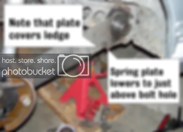
Note that on the fully relaxed spring plate that its lower edge is on or near the lower left-hand torsion bar cover bolt hole. This, of course, is coming off the factory setting. If someone else has reindexed the torsion bars, you might find anything, but we can still use the lower left-hand bolt hole as our reference point.
Because the plate is adjustable, as long as we start from the factory setting, we don’t need the protractor or inner spline vs outer spline calculation approach. This is cheating at its best.
Because the plate is adjustable, as long as we start from the factory setting, we don’t need the protractor or inner spline vs outer spline calculation approach. This is cheating at its best.
Remove the compression tool and pull the spring plate off the torsion bar splines. The old raggedy soft rubber inside spring plate factory bushing will be visible now. Pop it out.
Step 7: Good going! I’d thought you’d all have either given up or gotten maimed by Step 7.
Clean out the bushing recesses on both the torsion bar cover and torsion bar housing. Test fit your new inner and outer urethane bushings into them. If they do not fit flush (and they won’t) cut or grind away at the knobby bushing locators until they do fit flush.
Clean out the bushing recesses on both the torsion bar cover and torsion bar housing. Test fit your new inner and outer urethane bushings into them. If they do not fit flush (and they won’t) cut or grind away at the knobby bushing locators until they do fit flush.
Do your trimming slowly and test fit often so you don’t take off too much.
The temptation to skip this step and just try to pull the torsion bar cover down with longer bolts and compress the bushings will be strong, but all you’ll do is bend the cover and break a bolt or strip a thread.
Get out your metric tap and die set and chase the torsion bar housing threaded bolt holes clean of rust and dirt with an M10x1.5 tap. Use a little light 3-in-1 oil to help. Those holes do go all the way through, and are subject to water and dirt on the inside.
Prothane supplies a good silicone grease with its bushings, but not enough in my opinion. I’ve seen advice to use talcum powder to lube urethane bushings, but I slather black moly grease on them and so far (2002-present) nothing bad has happened.
The silicone grease is supposed to stop the classic urethane squeak that is common and irritating on street cars. In that all I work on is race cars, a squeak is not a real problem, but binding is. You want grease on all moving or contact surfaces.

Now (if you’re working on the right rear side of the car) screw a bolt into the lower left-hand corner hole of the torsion bar housing. This will be your guide and plate rest. Reverse this for the left rear.
Step 8: Reassembly
Place your (flush-fitting) inner bushing on the adjustable plate inside-facing boss and insert the bushing into the torsion bar housing recess over the torsion bar.
Place your (flush-fitting) inner bushing on the adjustable plate inside-facing boss and insert the bushing into the torsion bar housing recess over the torsion bar.
Rest the plate on the bolt.
Now, with lots of grease on the torsion bar splines, carefully fit the outer adjustable short plate over the splines, so that the outer plate is aligned evenly with the long plate as if they were one piece.
The long inner plate covers the ledge at full rest, and is going to have to be bent outwards to clear the ledge when we raise the plate assembly, so we don’t want to slide or hammer-tap the outer plate all the way down over the torsion bar splines just yet.
The long inner plate covers the ledge at full rest, and is going to have to be bent outwards to clear the ledge when we raise the plate assembly, so we don’t want to slide or hammer-tap the outer plate all the way down over the torsion bar splines just yet.
Attach the compression tool to the upper suspension arm nut and hook the bottom of the inner plate with the tool’s slot, and slowly lift the plate, watching out for the slot to fit, adjust itself, and not slip.

When you have the inner plate raised just above the ledge, slip on the outer urethane bushing and torsion bar cover, and screw your four long bolts into the torsion bar housing, with your two washer-spacers per bolt in place. Slowly tighten the bolts down in an X-pattern. Now you are pulling the outer plate down over the torsion bar splines. Don’t hurry. Tap the outer plate with a brass hammer a few times near the torsion bar cover as you go to equalize the stress.
You should see the inner plate move inwards so it is over the ledge. Lower the inner plate now to allow it to securely rest on the ledge, and do not guess at this. You must be sure. Be aware all the ledges out there are not guaranteed flat or straight after all these years of service.
Leave the compression tool in place. It is your safety.
Above: (A) Factory alignment notch for matching factory spring plate mark. (B) End of plate even with axle housing, applies for factory or adjustable plate.
Step 8: Almost Finished
Manhandle and shift the axle back into place, so that the axle flange and the spring plate can be bolted together.
Manhandle and shift the axle back into place, so that the axle flange and the spring plate can be bolted together.
Now insert the two axle housing end bolts loosely and slide the axle back all the way so that the axle housing is dead even with the end of the plate, as in the photo above.
Tighten the end bolts first, and you’ll see the adjustable plate bend just a bit, then finish with the bump stop bracket and it’s bolt. Make sure your alignment hasn’t changed. You might be lucky and have the alignment right, but let’s consider this your initial alignment until you test drive it.
Remove the compression tool so you can do the other side of the car.
Once you have the car on the ground again, you can raise or lower each side of the rear suspension to get your desired ride height.
FJC