Consider an air ride suspension setup.
AKA Project Farfemmuven
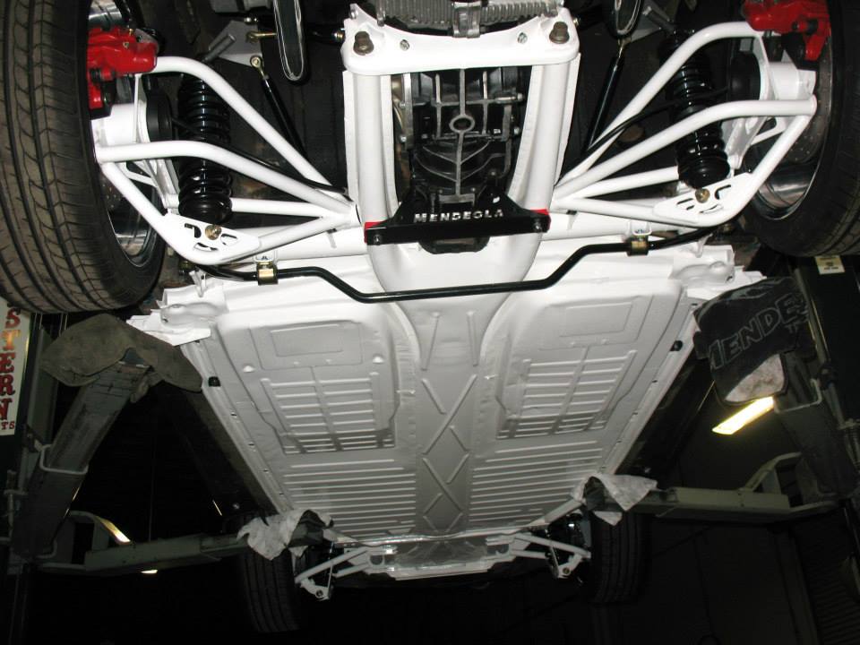
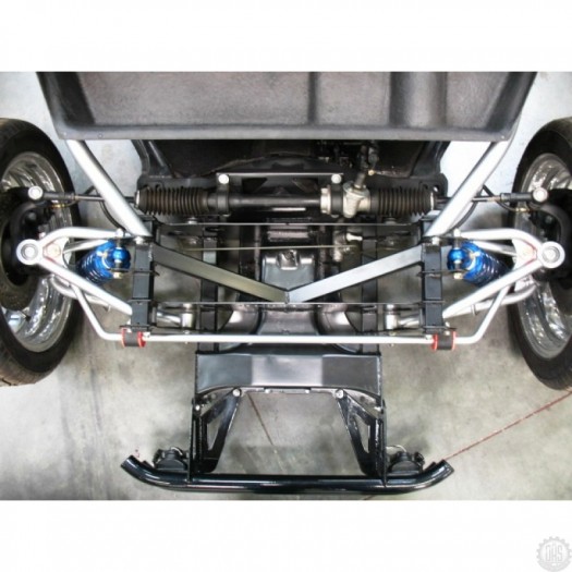
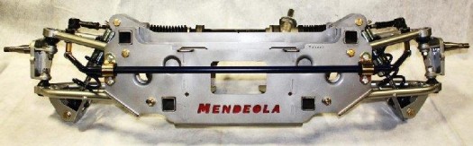
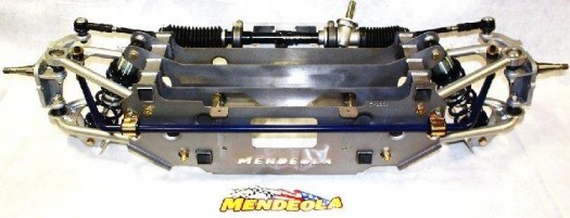
I would like to clear up a few points you might not be aware of about the Mendeola Suspesnion.
The rear arms are built with .5 degrees of camber at a 1.5 lowered ride height, and also has a camber adjusting plate that allows for even more camber adjustment. They also have toe and height adjustments. They are also the only rear trailing arms on the market that are available in a narrowed arm. This allows for a lot more tire and wheel combo’s. In fact we just fit 17×8 rear wheels with 215/40/17 tires under the rear of a low light ghia with out major fender mods.
Take a look at MendeolaSuspension.com for more info.
Also guys, the Mendeola Suspension prices are $3295 for the complete front kit spindle to spindle and $2395 for the complete rear kit. That’s less then 6k. Why have a 8-10k motor that hauls a$$ when you can’t stop or turn just as good? Just saying…..
http://www.shoptalkforums.com/viewtopic.php?t=127619
Ghia Road Course Setup
http://www.shoptalkforums.com/viewtopic.php?p=1187205#p1187205
Hi juki48,
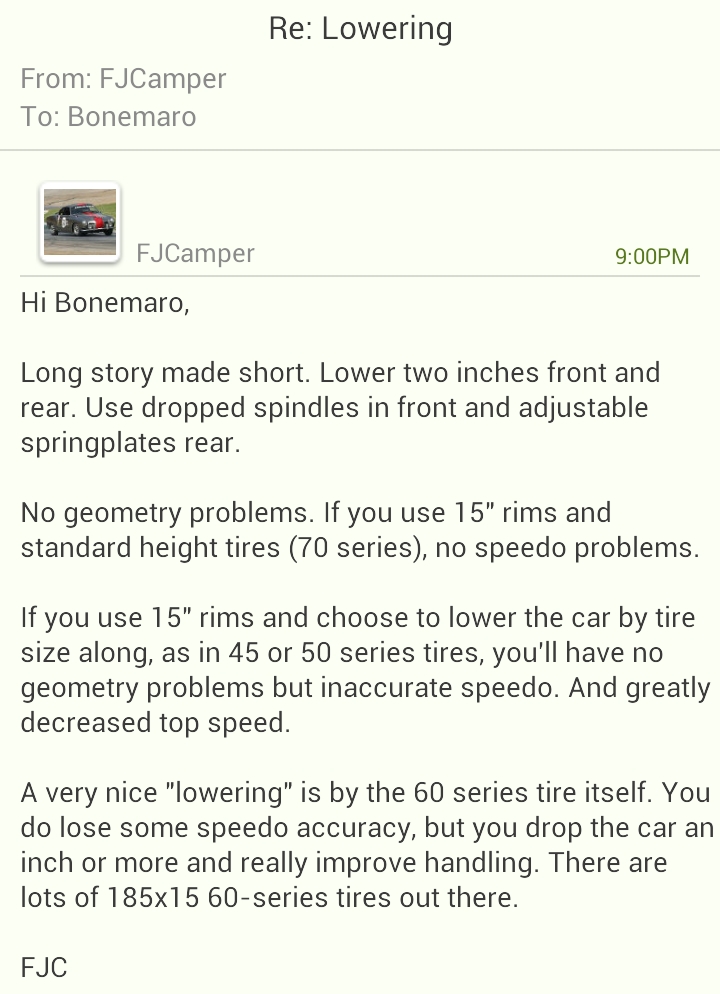
Dual 19mm bars on your ’74 will make your car feel very quick and responsive for street use. The front bar keeps the body roll down and keeps both front tires planted. The rear bar decreases the understeer and is the big contributor to the quick-response feel. The rear bar really enhances “turn-in” as in where you are steering into a turn and the car responds almost instantly.
But, for very high speed use, where you want understeer, a front bar alone is just right. High speed here means 100 mph sweepers where you want no sudden moves off course.
FJC
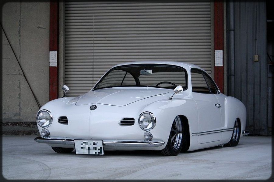
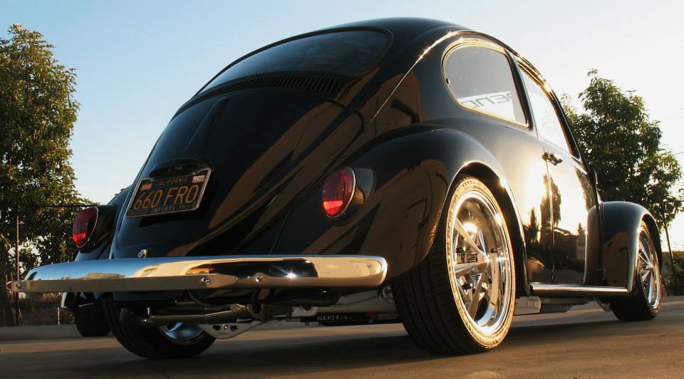
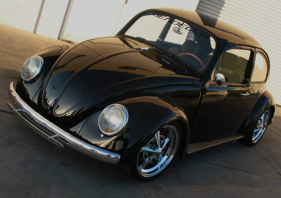
This stuff is VW porn.
Howdy, Jim
First off Jim, Thank you for your interest in our products.
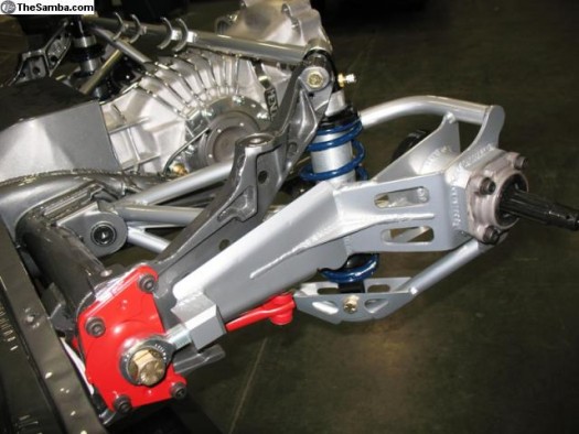
If you really want this car to handle and ride like a modern day sports car, I would say our complete Mendeola True Performance front and True Track narrowed rear kit would be the way to go. These will allow you to fit 17×7 wheels all around with 205/40/17s up front and 215/40/17s in the rear.
We also offer Big brake kits for well improved stopping. We offer 11″ cross drilled and vented front and rear brake kits with 4 piston Wilwood calipers on all four corners.
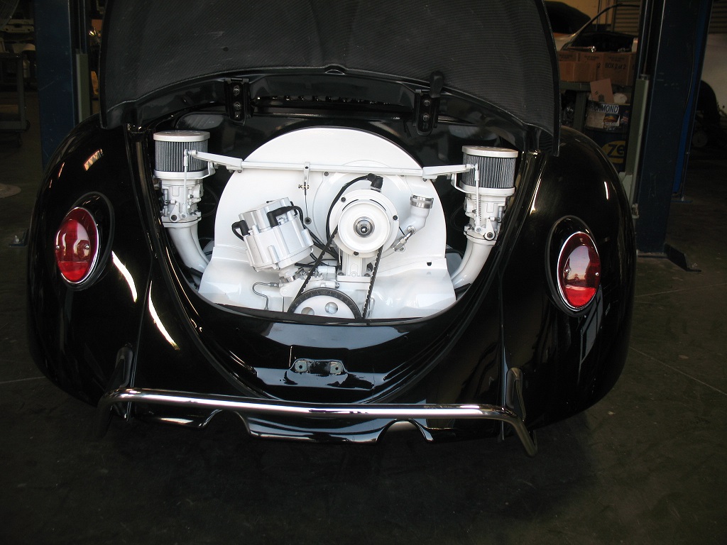
If you see yourself doing a lot of freeway driving or high speed driving, I would consider one of our 5 speed Porsche 915 Transaxle conversion kits. This will give you a trans that can take up to 300hp and let you run down the freeway at 80+ without running the engine above 3000 rpm.
Cost of these parts:
Suspension Front kit…..$3295
Suspension Rear kit …..$2395
Front Brake kit….$1280
Rear Brake kit…..$1480
915 trans kit…….$6500
You can find most of these on our website.
Please let us know if there is anything else we can do for you.
All the best to you my friend,
Kevin “Coolrydes” Zagar
CoolRydes So-Cal Customs &
MENDEOLA SUSPENSION
1695 Cactus Road
San Diego, Ca. 92154
619-710-4946 EXT.120
![404434_orig[1]](http://www.73ghia.com/wp-content/uploads/2014/06/404434_orig1.jpg)
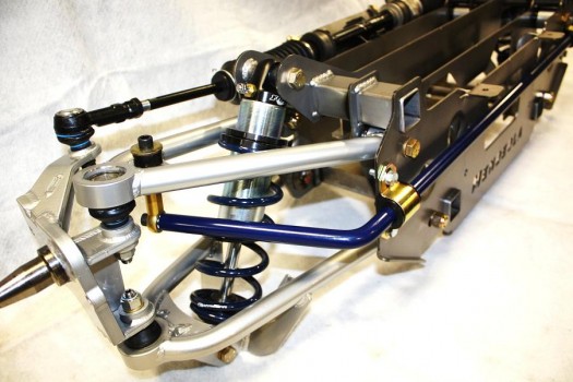
Karmann Ghia Chassis…
![2514247_orig[1]](http://www.73ghia.com/wp-content/uploads/2014/06/2514247_orig11.jpg)
Swing to IRS, the Hard Way
VWs set up for drag racing typically use what is known as “Swing Axles” in the back. The advantages are simplicity, strength and relatively easy to set up. The disadvantages are the severe wheel alignment change as the suspension goes through its full travel. Both extreme degrees of camber change (tip in or out at the top and bottom) as toe changes (pidgeon toed or people toed).
I haven’t been completely satisfied with the way car has been working with the swing axle set-up. Haven’t been for quite some time. Although I have been getting fair results, there have been compromises that needed to be made because of its limitations. I decided that the end of the 2009 season was time for the “Big Project,” and although there are fairly easy ways to do it, as in most things on this ride, I want to do it “My Way.”
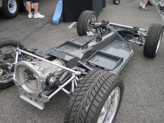
The Big Project is a change of wheels and rear suspension. The U-jointed swing axles we have run since 2003 are giving way for Independent Rear Suspension or IRS. This will feature a narrowed rear track with custom tubular control arms, Big 930 Porsche CVs, Mark Williams axles, coil-over shocks, four corner disc brakes and “Micro Stub” rear hubs. Wider wheels and tires will go along with these changes. American Racing’s Trak Stars are the wheels I’ve been looking to use for this project ever since I started thinking about it. Along with the spindle mount front wheels, the overall look will be different and very aggressive. Maybe it will scare the competition!
The major benefit will be better rear wheel alignment throughout the suspension travel, and the tires will stay square to the track surface and hopefully give more efficient operation. Increased safety is another benefit. There will be much less risk of losing control in the event of an axle failure. It is also looking like we’ll see a weight reduction both front and rear to the tune of about 60 pounds overall.
Once the existing drivetrain is removed, we began the mock-up by slipping the CV drive flange onto the transaxle, and then positioning the wheel/tire/hub combo into the wheel well in the position where it should be. By taking a measurement between CV flanges on trans and drive hub, a dummy mock-up axle was made that bolts on the flanges and is the length necessary to position the wheel where it needs to be. Basically, it’s a length of tubing with flanges at both ends.
Since it’s on center with the output flanges on the trans, the wheel will be on center as well when we start fabricating the control arms. Although absolute on-center wheel positioning is not so critical with IRS, having it as close as possible, will make it so the joint doesn’t “work” any more than it needs to.
My original plan was to leave the upper spring mount in it’s existing location, but after some rough mocking up with cardboard templates, it was apparent that too many compromises would have to be made to the design of the control arm to fit the coil spring into the same location it’s been in. So, a fairly difficult, yet at the same time, easy decision was made to cut out the existing rear support structure and start fresh.
To get the control arm design to be the way I wanted, I decided to raise the upper shock mount so that the lower mount could be on top of the control arm, and out of the way of the diagonal bars and the outer CV joint. This required removal of a portion of the rear package tray, as the upper shock mount will be above the stock package tray location. Since I will be “mini-tubbing” the wheel wells, a little more sheet metal work in the package tray is not a big deal.
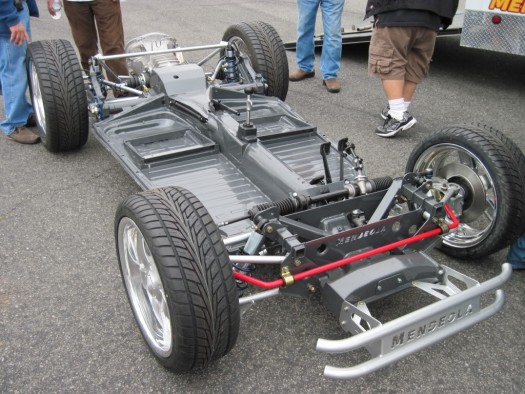
With the new rear support structure tacked in, I moved to making the custom brackets and tabs I would need. All of the control arm mounts are going to be located off the rear torsion housing. This makes set-up much simpler. The pivot bracket will have three mounting holes. The bottom one on center of the torsion tube and the other two at one inch spacing above that. Call it an educated guess as to determining their location. The pivot point on center will be as if it was in the stock location. The two points higher up will put the pivot arm’s “push point” on a higher weight center. Will it improve handling? Only time will tell.
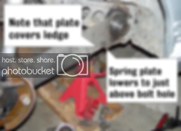
With the inner bracket tacked in level with the chassis, fab work on the control arm begins. First, the outer hub bracket, then the inner control arm stub. After that it’s simply a matter of “Connect the Dots.” An outer pivot bracket is then made and will be welded to the end of the torsion tube after the “stock style” spring plate flange is removed. We can then finish off the basic control arm with the addition of the outer straight forward bar. The control arm pivots on 3/4″ super duty rod ends which are adjustable in and out.
To enable adjustment of rear wheel alignment, a plate which is cut at a slight angle, will be sandwiched between the hub and the hub mounting plate. By rotating this plate, a precise rear wheel alignment can be achieved.
When the first control arm is complete, the arm and it’s bracketry is mirrored for the other side. Once both sides are complete, it’s down to finish and detail work, then measuring for axles.
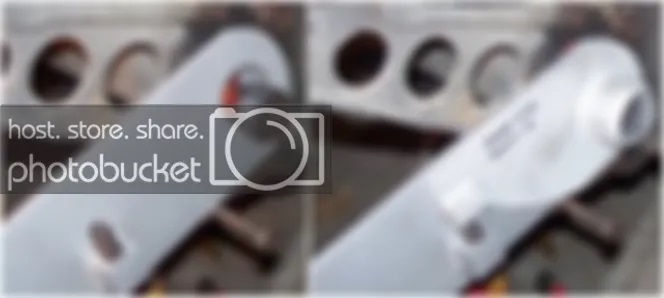
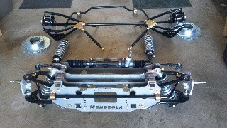
The axles ended up 11.875″ long, made from 300m material and were ordered from Mark Williams. Fair price, great service!
The pan, once all the finish welding was done was sent over to Blast Tech in Fresno for powdercoating. Since first putting this pan into service in 2005, this will be it’s first trip to the powdercoaters. The finished job is simply incredible! A week from start to finish, and it was received clean with no trace of sand residue. The satin black finish is actually glossier than the gloss black I have received from other powdercoaters. The control arms, tie rods and a few other various pieces were done in gloss black, and it’s like a mirror. Very pleased with Blast Tech’s work!
Now that it all fits and functions as envisioned, the Big Question is, “How will it work?”
The Front End
Next up is converting the front end to the new American TrakStar spindle mount front wheels. While it seemed that Anglia spindle wheels would be the easier conversion since the inner bearing has the same inner diameter as the stock linkpin, it turns out that Strange spindle wheels are easier. This due to the OUTER bearing which would only require a skim cut to fit, and the threads are good as is. The Anglia outer bearing is much smaller and would require either reducing and rethreading the end of the spindle or finding a conversion bearing.
I opted for the Strange. All that is required is to make a bushing for the inner bearing and taking a .030″ skim cut on the outer spindle journal. Very simple.
I also bought a Wilwood disc brake kit to use on the American wheels. The brake hat bolts right on to the back of the wheel. The biggest hurdle was that the bracket for the caliper was made for a P&S dragster spindle. I used this as a pattern to make caliper mounts to fit the VW spindle. All in all, a painless conversion that took about a half day and a foot long piece of 3/8″ x 4″ 6061 aluminum.
With all American style wheels and brakes, the only original brake part that remained was the cast iron dual circuit master cylinder. I decided this was the time to replace that, even though it was new last season. I felt the four piston calipers at the rear, along with the disc brakes up front would need more volume than the stock MC could provide. Wilwood again supplied the aluminum dual circuit MC with optional remote mount reservoirs.
With the elimination of the stock style MC, there was no sense in keeping the stock brake lines with a bunch of metric to AN adapters. It will be completely converted to all AN with stainless steel lines.
That completes the chassis work. With clean-up and detail work and elimination of all unused brackets and tabs, the pan will go in for a satin black powder coat finish.
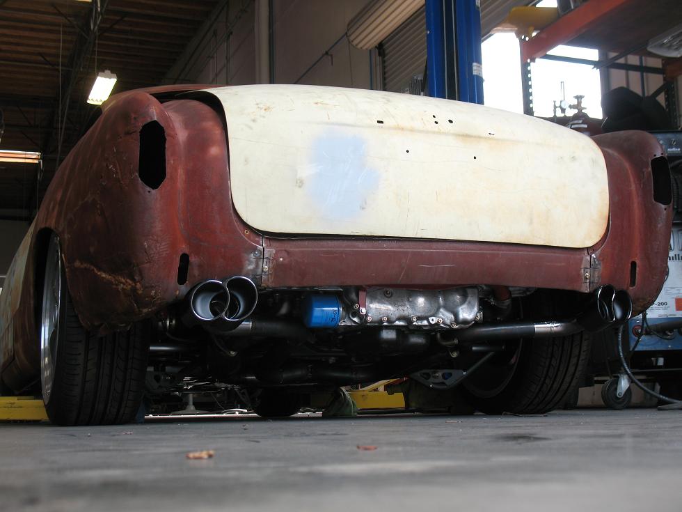
The Body Work
Yes, I cut the car. Some will consider this the ultimate sin. In fact I swore I would never cut the car when this voyage first began. This was because of what I did to my 1970 T/A Challenger “Back in the Day.” I always had illusions of being able to take the Ghia back to stock if I so chose. I never imagined that the car would create its own “history” and as such, is probably worth more as a race car than it ever would as a stocker.
At any rate, I was fairly gentle. The narrower rear track made it necessary to provide a bit more room to the inside. I decided on the “Mini-Tub” approach. This method involves removing the inner half of the stock wheel housing, moving it inboard and welding it back in. I ended up building a new inner half from sheet steel and still welded it in so the body maintains its integrity.
My good friend Bob Welker did most of the work cutting out the “hole” helping me fit the new stuff and doing the finish work. I made the parts, and did the welding.
Bob is a true craftsman and has been “The Man” behind more than a few show winners and magazine feature cars. I couldn’t have thought of anyone I would rather have doing this work. Thanks Bob!
With the fabulous and very precise job that Bob did with cutting the opening, fitting the new innerwheel tub was fairly easy. Once finished, I doubt most people will even notice as the entire engine bay was repaired and refinished back to the blue color that the rest of the car is.
Sorry… the pictures were linked from the original post. Sadly, these are the best I can save.
This topic can be found at: https://shoptalkforums.com/viewtopic.php?f=51&t=137122Read the original post. It seems there are some issues with these.